Molded product appearance, size, fit
1)Surface defects are not permitted: missing material, scorching, whitening, white lines, burrs, blistering, tearing (or cracking, breakage), baking marks, wrinkles, etc.
2)Weld lines: Generally, the length of weld lines for round perforations should not exceed 5mm, and the length of weld lines for irregularly shaped perforations should be less than 15mm. The weld line strength must pass functional safety testing.
3)Shrinkage: No shrinkage is allowed in obvious areas of the surface; slight shrinkage (not perceptible to the touch) is permitted in less obvious areas.
4)The flatness of small products should generally be less than 0.3mm. For products requiring assembly, assembly requirements must be met.
5)No air bubbles or material defects are allowed in obvious areas of the surface. Generally, products should not have air bubbles.
6)The geometric shape and dimensional accuracy of the product should conform to the requirements of the official and valid mold drawings (or 3D files). Product tolerances must adhere to tolerance principles: negative tolerances for shaft dimensions and positive tolerances for hole dimensions. Customer-specified tolerances will be followed.
7)Product wall thickness: The product wall thickness should generally be an average thickness. Non-average wall thickness should meet the drawing requirements. The tolerance should be -0.1mm according to the mold characteristics.
8)Product fit: Top shell and bottom shell fit: Surface misalignment should be less than 0.1mm, and there should be no scraping sensation. Holes, shafts, and surfaces with fit requirements should ensure the fit interval and use requirements.
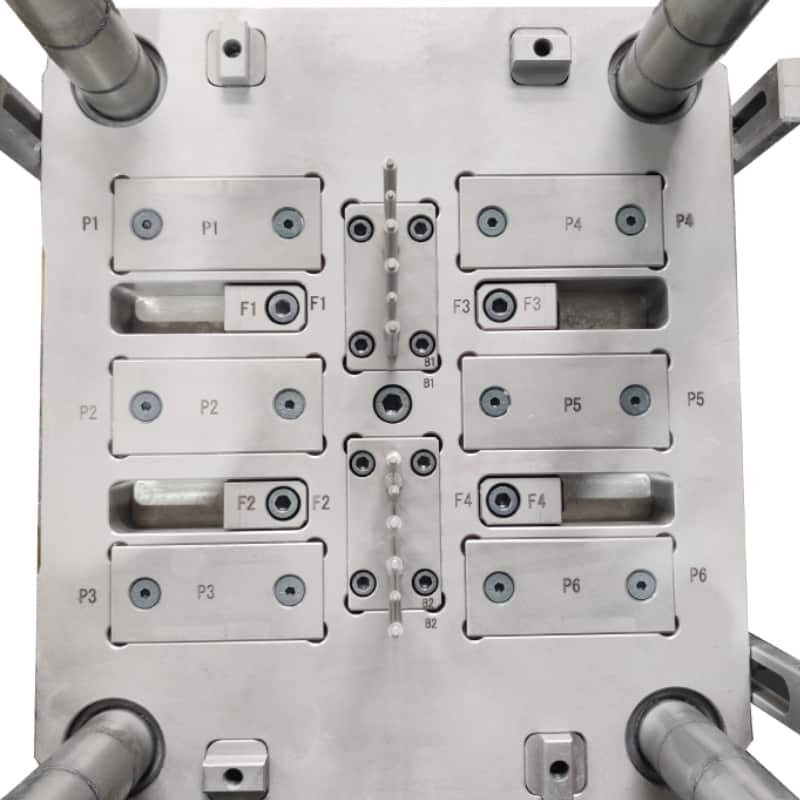
Mold appearance
1) The mold nameplate should be complete, with clear characters and neat arrangement.
2) The nameplate should be fixed to the mold base near the template and reference corner. The nameplate should be reliably fixed and not easily peeled off.
3) Plastic block water nozzles should be used; if the customer has other requirements, they should be followed.
4) The cooling water nozzles should not protrude from the mold base surface .
5) The cooling water nozzles need to be countersunk, with countersunk diameters of 25mm, 30mm, and 35mm. The nozzle openings should be chamfered, and the chamfers should be consistent.
6) The cooling water nozzles should have inlet and outlet markings.
7) The markings (English characters and numbers) should be larger than 5/6, positioned 10mm directly below the water nozzle, and the lettering should be clear, aesthetically pleasing, neat, and evenly spaced.
8) Mold accessories should not affect the lifting and storage of the mold. Exposed components such as hydraulic cylinders, water nozzles, and pre-reset mechanisms should be protected by support legs.
9) Support legs should be installed using screws passing through them and fixed to the mold base. For excessively long support legs, externally threaded posts can be machined and fastened to the mold base.
10) The ejector hole size of the mold should meet the requirements of the specified injection molding machine. Except for small molds, a single center ejector should not be used.
11) The locating ring should be reliably fixed. The ring diameter is usually 100mm or 250mm (depending on the machine model). The locating ring should protrude 10-20mm above the base plate, unless otherwise specified by the customer.
12) The external dimensions of the mold should meet the requirements of the specified injection molding machine.
13) For molds with directional installation requirements, the installation direction should be indicated by an arrow on the front or rear mold plate. The word “UP” should be next to the arrow, and both the arrow and the text should be yellow, with a text height of 50mm.
14) The mold base surface should be free of pits, rust, excess lifting rings, water inlets/outlets, oil holes, and other defects that affect the appearance. 15.
The mold should be easy to lift and transport. Mold components should not be disassembled during lifting, and lifting rings should not interfere with water nozzles, hydraulic cylinders, pre-reset rods, etc.
Mold material and hardness
1) The mold base should be a standard mold base that conforms to the standards.
2) The materials for mold forming parts and the gating system (core, moving and fixed mold inserts, movable inserts, runner cones, ejector pins, sprue bushings) should be materials with performance higher than 40Cr.
3) When molding plastics that are easily corroded by the mold, the forming parts should be made of corrosion-resistant materials, or the forming surfaces should be protected against corrosion.
4) The hardness of the mold forming parts should not be less than 50 HRC, or the surface hardening treatment should have a hardness higher than 600 HV.
Ejection, Reset, Insertion and Removal of Core, Part Removal
1) Ejection should be smooth, without jamming or abnormal noise.
2) The surface of the angled ejector should be polished, and the angled ejector surface should be lower than the core surface.
3) Sliding parts should have oil grooves, and the surface should be nitrided to a hardness of HV700 or higher.
4) All ejector pins should have anti-rotation positioning, and each ejector pin should be numbered.
5) The ejection distance should be limited by limit blocks.
6) The return spring should be a standard part, and the ends of the spring should not be ground or cut off.
7) The slider and core puller should have stroke limits. Small sliders should be limited by springs; if springs are inconvenient to install, ball screws can be used. Hydraulic cylinder core pullers must have limit switches.
8) Slider core pullers generally use angled guide posts, and the angle of the angled guide post should be 2°~3° smaller than the angle of the slider locking surface. If the slider stroke is too long, hydraulic cylinder puller should be used.
9) When the end face of the hydraulic cylinder core puller is covered, the hydraulic cylinder should be equipped with a self-locking mechanism.
10) Large sliders with a slider width exceeding 150 mm should have a wear-resistant plate underneath. The wear-resistant plate material should be T8A, with a hardness of HRC50~55 after heat treatment. The wear-resistant plate should be 0.05~0.1 mm higher than the large surface and have oil grooves.
11) The ejector pin should not move up and down.
12) Add barbs to the ejector pin. The direction of the barbs should be consistent, and the barbs should be easy to remove from the product.
13) The fit clearance between the ejector pin hole and the ejector pin, the length of the sealing section, and the surface roughness of the ejector pin hole should meet the relevant enterprise standards.
14) The product should be easy for the operator to remove.
15) To prevent the product from easily following the inclined ejector during ejection, grooves or textures should be added to the ejector pin.
16) The ejector block fixed to the ejector pin should be firm and reliable. The non-forming parts around the ejector pin should be machined with a 3°~5° slope, and the lower perimeter should be chamfered.
17) There should be no iron filings or debris in the oil passage holes on the mold frame.
18) The end face of the return rod should be flat and free of spot welds. 19. The bottom of the blank head has no gasket and is spot-welded. 20.
The sprue plate of the three-plate mold slides smoothly and is easy to pull open.
21) The limit rods of the three-plate mold should be arranged on both sides of the mold installation direction, or a pull plate should be added outside the mold frame to prevent interference between the limit rods and the operator.
22) The oil and air passages should be unobstructed, and the hydraulic ejection reset should be in place.
23) An exhaust port should be opened at the bottom of the guide sleeve.
24) The locating pins should be installed without gaps.
Cooling and heating systems
1) The cooling or heating system should be fully unobstructed.
2) The seal should be reliable; the system should not leak under 0.5 MPa pressure and should be easy to maintain.
3) The size and shape of the sealing groove on the mold frame should meet the relevant standard requirements.
4) Grease should be applied before installing the sealing ring, and it should protrude above the mold frame surface after installation.
5) Water and oil flow channel baffles should be made of materials that are not easily corroded.
6) The front and rear molds should use a centralized water supply system.
7) The diameter of the cooling water channels should be between 8 and 12 mm.
Gating system
1) The gate design should not affect the product’s appearance and should meet assembly requirements.
2) The runner cross-section and length should be rationally designed. While ensuring molding quality, the flow path should be shortened as much as possible, reducing the cross-sectional area to shorten filling and cooling time, while minimizing plastic loss in the gating system.
3) For three-plate molds, the section of the sprue on the back of the front plate should be trapezoidal or semi-circular.
4) Three-plate molds should have a sprue cut-off on the sprue plate. The sprue inlet diameter should be less than 3 mm, and the ball head should have a 3 mm deep step recessed into the sprue plate.
5) The ball head pull rod should be reliably fixed, either by pressing it under the locating ring, using a headless screw, or by pressing it with a pressure plate.
6) The gate and runner should be machined according to the dimensions specified in the drawings; manual machining with a grinding machine is not allowed.
7) Point gates should be installed according to specifications.
8) The front end of the runner should have an extended section as a cold slug well.
9) The Z-shaped undercut of the pull rod should have a smooth transition.
10) The runners on the parting surface should be circular, and the front and rear molds should not be misaligned.
11) Submerged gates on the ejector pins should have no surface shrinkage.
12) The diameter and depth of the cold slug well on transparent products should meet design standards.
13) The slug stub should be easily removed, with no gate marks on the product’s appearance, and no residual slug stub at the assembly point.
14) For hook-type submerged gates, both insert parts should be nitrided to a surface hardness of HV700.

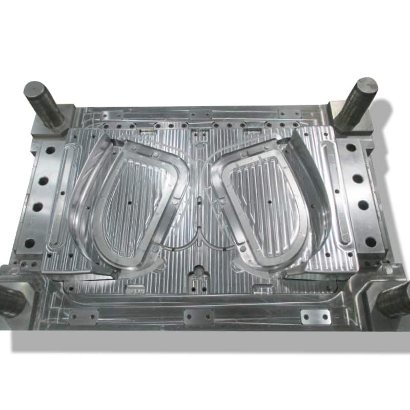
Molding part, parting surface, venting groove
1) The surfaces of the front and rear molds should be free from unevenness, pits, rust, and other defects that affect appearance.
2) The inserts should fit the mold frame with a clearance of less than 1mm around the rounded corners.
3) The parting surface should be clean, tidy, and free from grinding gaps with a hand-held abrasive wheel; the sealing area should be free from depressions.
4) The depth of the venting groove should be less than the overflow value of the plastic.
5) Inserts should be properly fitted, placed smoothly, and reliably positioned.
6) Inserts, cores, etc., should be reliably positioned and fixed; round parts should have anti-rotation features; and inserts should not be padded with copper or iron sheets.
7) The ejector pin end face should be consistent with the core. 8.
The forming parts of the front and rear molds should be free from undercuts, chamfers, and other defects.
9) Ejection of ribs should be smooth.
10) For multi-cavity molded products, the left and right parts should be symmetrical, and L or R should be marked. If the customer has requirements for position and size, these requirements should be met, generally added in a place that does not affect the appearance and assembly, with a font size of 1/8.
11) The locking surfaces of the mold base should be properly fitted, with at least 75% contact area.
12) Ejector pins should be placed close to the side walls and next to ribs and bosses, and larger ejector pins should be used.
13) Identical parts should be numbered 1, 2, 3, etc.
14. All contact surfaces, insertion surfaces, and parting surfaces should be properly fitted.
15) The sealing portion of the parting surface should meet design standards. For medium and small molds, 10-20mm; for large molds, 30-50mm; the remaining portion should be machined to allow for clearance.
16) Texture and sandblasting should be uniform and meet customer requirements.
17) For products with specific appearance requirements, screws on the product should have anti-shrinkage measures.
18) Screw posts with a depth exceeding 20mm should use ejector tubes.
19) The wall thickness of the product should be uniform, with deviation controlled below ±0.15mm.
20) The width of ribs should be less than 60% of the wall thickness of the surface.
21) The inserts on the angled ejectors and sliders should have reliable fixing methods.
22) When the front mold is inserted into the rear mold or the rear mold is inserted into the front mold, there should be beveled surfaces around the perimeter for locking and machining to avoid gaps.
Injection molding process
1) Under normal injection molding process conditions, the mold should possess stability in injection molding production and repeatability in process parameter adjustment.
2) The injection pressure during injection molding should generally be less than 85% of the rated maximum injection pressure of the injection molding machine.
3) The injection speed during injection molding should not be less than 10% or exceed 90% of the rated maximum injection speed during the three-quarters stroke.
4) The holding pressure during injection molding should generally be less than 85% of the actual maximum injection pressure.
5) The clamping force during injection molding should be less than 90% of the rated clamping force of the applicable machine model.
6) During injection molding, the removal of the product and sprue should be easy and safe (generally, each taking no more than 2 seconds).
7) For molds with inserts, the inserts should be easy to install and reliably fixed during production.
Packaging and transportation
1) The mold cavity should be thoroughly cleaned and sprayed with anti-rust oil.
2) Sliding parts should be lubricated.
3) The sprue bushing inlet should be sealed with grease.
4) The mold should be equipped with locking plates, the specifications of which should meet design requirements.
5) Spare parts and easily damaged parts should be complete, with a detailed list and supplier names attached
6) Water, liquid, gas, and electricity inlets and outlets of the mold should be sealed to prevent foreign objects from entering.
7) The outer surface of the mold should be painted; if the customer requests it, it should be done accordingly.
8) The mold should be packaged in a moisture-proof, waterproof, and impact-resistant manner; if the customer requests it, it should be done accordingly.
9) Mold product drawings, structural drawings, cooling and heating system drawings, hot runner drawings, supplier details for spare parts and mold materials, instruction manual, trial molding report, factory inspection certificate, and electronic documents should all be complete.
